+86 10-53676895
1368690224@qq.com
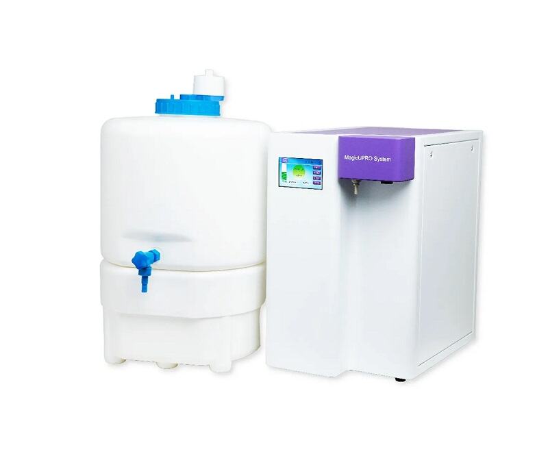
As an indispensable piece of equipment in modern scientific research laboratories, the ultrapure water system—distinguished by its exceptional performance and precision technology—provides researchers with the assurance of the purest possible water supply. So, how exactly does this remarkable device operate? And how does it ensure that every single drop of water meets the rigorous standards of ultrapurity? Join us now as we unveil the mysteries behind the laboratory ultrapure water system.
What are impurities in water?
To understand laboratory ultrapure water systems, one must first understand the impurities in water that these systems are designed to remove. Impurities found in water are typically classified into nine categories.

Working Principle of Ultrapure Water Systems
The working principle of a laboratory ultrapure water system involves the pretreatment of tap water using precision filters and activated carbon cartridges to remove particulate matter (such as sediment) and adsorb odors, thereby rendering the water cleaner. This pretreated water then undergoes purification and desalination via a reverse osmosis (RO) unit. The purified water is collected and stored in a reservoir; at this stage, its quality meets the national standard for Grade III laboratory water, while the wastewater generated by the RO process is discharged. The RO-purified water is subsequently passed through a purification column for deep desalination, yielding Grade I water or ultrapure water. Finally, to meet specific user requirements, additional downstream modules—such as UV sterilization, microfiltration, or ultrafiltration units—may be added to the system to eliminate residual bacteria, particulates, pyrogens, and other contaminants from the ultrapure water.
The ultrapure water produced by such systems typically exhibits a resistivity greater than 18 MΩ·cm, or approaches the theoretical limit of 18.25 MΩ·cm (at 25°C).
Laboratory Water Specifications
The source water (feedwater) used for analytical laboratory applications should consist of potable water or water of appropriate purity.
Laboratory water for analytical purposes is classified into three grades: Grade I, Grade II, and Grade III.
☆ Grade III Water: This represents the lowest grade of laboratory-purity water. It is recommended for applications such as washing glassware, filling water baths and autoclaves, and serving as the feedwater for ultrapure water systems.
☆ Grade II Water: Generally used for routine laboratory applications, such as the preparation of buffers, pH solutions, and microbiological culture media; supplying water to ultrapure water systems, clinical biochemistry analyzers, incubators, and accelerated aging chambers; and preparing reagents for chemical analysis or synthesis.
☆ Grade I Water: Typically reserved for rigorous experimental applications, such as the preparation of HPLC mobile phases; the preparation of GC blanks and sample dilutions; high-precision analytical techniques (e.g., HPLC, AA, ICP-MS); the preparation of buffers and mammalian cell culture media; the preparation of reagents for molecular biology applications (e.g., DNA sequencing, PCR amplification); and the preparation of solutions for electrophoresis and hybridization experiments.

Standard Water Quality Classifications
01. Pure Water
Pure water—also referred to as purified water—represents the lowest level of purification; specifically, it corresponds to the national standard for Grade III laboratory water. It typically exhibits an electrical conductivity ranging from 1 to 10 μS/cm. It can be produced using a single weak-base anion exchange resin, reverse osmosis, or single distillation; it contains no additives, is colorless and transparent, and is safe for direct consumption. "Space water" and distilled water sold on the market are both classified as pure water. Typical applications for pure water include the cleaning of glassware and use in washing machines.
02. Deionized Water
Deionized water represents a water quality level situated between standard pure water and Laboratory Grade II water; its conductivity typically ranges from 0.1 to 1.0 μS/cm (with a resistivity between 1.0 and 10.0 MΩ·cm). It is produced using mixed-bed ion exchange involving strong anion exchange resins. While it may contain relatively higher levels of organic matter and bacterial contamination, it is capable of meeting a variety of needs, such as cleaning, preparing analytical standard samples, formulating reagents, and diluting samples.
03. Laboratory Pure Water
Typically, "Laboratory Pure Water" refers to water that meets the national standard for Grade II water. This standard demands not only high purity in terms of ionic content but also low concentrations of organic matter and microorganisms. Typical specifications include a conductivity of <0.1 μS/cm (resistivity >10 MΩ·cm), a Total Organic Carbon (TOC) content of less than 50 ppb, and a bacterial count of less than 1 CFU/mL. This water quality is suitable for a wide range of applications, ranging from reagent preparation and solution dilution to the formulation of nutrient media for cell culture and microbiological research. Laboratory pure water can be produced via double distillation, or by integrating multiple technologies—such as reverse osmosis (RO) and ion exchange/EDI—potentially combined with adsorption media and UV irradiation.

04. Laboratory Ultrapure Water
"Laboratory Ultrapure Water" represents the ideal water quality, surpassing the standards for Laboratory Grade I water. In terms of resistivity, organic content, particulate matter, and bacterial levels, it approaches the theoretical limits of purity. It is produced by first undergoing preliminary purification via ion exchange, RO membranes, or distillation, followed by a final polishing step using nuclear-grade ion exchange resins to achieve ultrapure water. Typically, ultrapure water achieves a resistivity of 18.2 MΩ·cm, a TOC content of <10 ppb, and is filtered to remove particles of 0.1 μm or smaller, with a bacterial count of less than 1 CFU/mL. Ultrapure water is suitable for meeting the requirements of various precision analytical experiments, such as High-Performance Liquid Chromatography (HPLC), Ion Chromatography (IC), and Inductively Coupled Plasma Mass Spectrometry (ICP-MS).
Common Water Purification Technologies
Common purification methods include ion exchange, activated carbon adsorption, microporous membrane filtration, reverse osmosis desalination, ultrafiltration, and UV digestion for TOC reduction.
How to Select a Pure Water System
Selection should be based on the following key points:
Clarify the Feedwater Source: It is essential to determine whether the system will utilize municipal tap water or pre-purified water (such as deionized or distilled water) as its input source. If the quality of the municipal tap water is poor (e.g., TDS ≥ 300 ppm), enhanced pre-treatment modules—such as water softeners, KDF filters, etc.—should be added to the configuration.
Determine Water Consumption: User water requirements must be evaluated based on the following aspects: Water Dispensing Method—specifically, whether water is drawn continuously or intermittently during operation, and whether there are specific requirements regarding outlet pressure, storage tanks, tubing, etc.; Peak Demand—the duration of peak usage periods and the corresponding volume requirements, which help determine the appropriate machine specifications and configuration; and Daily Consumption—calculated separately for pure water and ultrapure water requirements to further refine the selection of the specific product model.
Align with Experimental Requirements: Select the system based on the specific standards of the analytical tests being performed. Consider whether the experiments impose specific limits on parameters such as TOC (Total Organic Carbon), bacterial count, pyrogens, or particulate matter. In other words, identify the specific application area or the analytical instruments with which the system will be paired—such as Atomic Absorption Spectrometry (AAS), microbiological analysis, general chemistry, cell culture, biochemical analysis, etc. Clearly defining these parameters ensures the precise selection of the appropriate product model and specifications.
I. Introduction to EDI Ultrapure Water Systems
EDI (Electrodeionization) ultrapure water treatment equipment—also known as an electrodeionization system—represents a novel technology for producing ultrapure (or high-purity) water by organically combining electrodialysis membrane separation technology with ion exchange technology. It utilizes the polarization phenomenon inherent in the electrodialysis process to electrochemically regenerate the ion exchange resins packed within the system's dilute water chambers. Operating under the influence of a DC electric field, the system drives the directional migration of dissolved ions (electrolytes) within the water as they pass through the separation membranes; by leveraging the selective permeability of these membranes toward specific ions, the system effectively purifies the water.
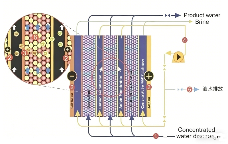
II. Basic Working Principles of EDI
EDI is a pure water production technology that integrates ion exchange, ion exchange membrane, and ion electromigration (electrodialysis) technologies. This technology leverages the deep desalination capabilities of ion exchange to overcome the limitations of electrodialysis—specifically, its potential for incomplete desalination due to polarization effects. Simultaneously, it harnesses the electrodialysis polarization phenomenon to induce the dissociation of water molecules, generating H+ and OH- ions. These generated ions serve to continuously regenerate the ion exchange resins, thereby ensuring that the resins remain in their optimal state for effective purification. An EDI stack primarily consists of an alternating arrangement of cation exchange membranes, concentrate compartments, anion exchange membranes, diluate compartments, and positive and negative electrodes. Ion exchange resins are packed between the cation and anion exchange membranes to form individual treatment units, which constitute the diluate compartments; these units are separated from one another by mesh spacers, thereby forming the concentrate compartments. Under the influence of a direct current electric field, cations and anions within the ion exchange resins in the diluate compartments migrate—along the channels formed by the resins and membranes—toward the negative and positive electrodes, respectively. Cations pass through the cation exchange membranes, while anions pass through the anion exchange membranes, entering the concentrate compartments to form a concentrate stream. Simultaneously, cations and anions present in the EDI feed water undergo exchange with the hydrogen ions and hydroxide ions within the ion exchange resins, resulting in the production of ultrapure water (or high-purity water). The application of a "super-limiting current" induces the electrolysis of water, generating a copious supply of hydrogen ions and hydroxide ions that continuously regenerate the ion exchange resins. In contrast to traditional ion exchange processes—where resins require intermittent chemical regeneration once saturated—the resins within an EDI stack are continuously regenerated through the electrolysis of water; thus, the operation is continuous and requires no chemical regeneration using acids or bases.
An EDI system separates the feed water into three distinct streams: a pure water stream, a concentrate stream, and an electrode rinse stream. The pure water stream (90–95% of the total flow) constitutes the final product water; the concentrate stream (5–10%) can be recycled for further processing; and the electrode rinse stream (1%) is discharged.

III. Characteristics of EDI Systems
EDI systems do not require chemical regeneration and are capable of continuous operation; consequently, they eliminate the need for the acid and alkali solutions—as well as the wastewater discharge—typically associated with the regeneration of mixed-bed ion exchange equipment in traditional water treatment processes. Their key characteristics are as follows:
The Basic Water Purification Process of EDI:
(1) Continuous operation, resulting in stable product water quality.
(2) Easy to implement fully automated control.
(3) No need for acid or alkali regeneration.
(4) No downtime caused by regeneration; saves on regeneration water and eliminates the need for regeneration wastewater treatment facilities.
(5) High water recovery rate (up to 95%).
EDI units belong to the category of fine water treatment systems. They are typically used in conjunction with Reverse Osmosis (RO) to form an ultrapure water treatment system comprising pretreatment, RO, and the EDI unit, thereby replacing the mixed-bed ion exchange equipment found in traditional water treatment processes. The feedwater requirement for an EDI unit is a resistivity of 0.025–0.5 MΩ·cm—a standard that RO units are fully capable of meeting. EDI units can produce ultrapure water with a resistivity exceeding 15 MΩ·cm.
For high-purity water systems, the RO + EDI process represents an ideal choice—whether one considers factors such as water quality, performance, and operation, or aspects such as operating costs and environmental protection.
III. Advantages and Disadvantages of Various Technical Processes for EDI Equipment
Currently, there are approximately three main technical approaches utilized by complete EDI ultrapure water systems to produce ultrapure water. Each of these three processes possesses its own distinct advantages as well as disadvantages. The first approach is the traditional method of producing ultrapure water using ion exchange resins. This process offers clear advantages: the initial capital investment for the equipment is low, and the equipment occupies a relatively small footprint. However, after prolonged operation, the resins require regeneration; this regeneration phase results in significant waste of acids and alkalis, as well as associated pollution, making it a less environmentally friendly option.
Nowadays, ultrapure water system processes generally fall into three major categories; other processes are essentially derivatives created by combining and configuring these three fundamental categories in various ways. The advantages and disadvantages of these three processes are listed below:
1. The first process employed by specialized EDI ultrapure water systems (typically for the electronics industry) relies primarily on ion exchange resins. Its advantages lie in the low initial capital investment and the minimal space requirements; however, its disadvantages are equally evident: it necessitates frequent regeneration, which causes a certain degree of environmental damage.
2. The second process utilizes Reverse Osmosis (RO) technology as a pretreatment stage. The disadvantages of this process are even more significant than those of the first: the initial capital investment required is substantially higher than that of the first method. Its sole advantage is that the regeneration intervals for the specialized EDI ultrapure water equipment are relatively longer; however, this process still carries a certain potential for environmental pollution. 3. The third process also utilizes a reverse osmosis unit as the pretreatment equipment. Currently, this third method represents the most economical and environmentally friendly process available for producing ultrapure water; it eliminates the need for equipment regeneration procedures and results in virtually no environmental pollution. However, its drawback lies in the fact that the initial capital investment required remains relatively high compared to the two methods mentioned above.
III. Assessment of Contamination in EDI Equipment and Cleaning Methods
EDI Fouling Assessment and 8 Cleaning Methods
Although the inlet water conditions for EDI modules significantly reduce the likelihood of internal blockage, as equipment operating time extends, it remains possible for blockages to develop within the internal water channels of the EDI modules. This is primarily due to the presence of high concentrations of dissolved solutes in the EDI feed water, which leads to the precipitation of salts within the concentrate chambers. If the feed water contains high levels of calcium and magnesium ions (hardness exceeding 0.8 ppm), CO2. and has a high pH value, the rate of precipitation will be accelerated. When such situations arise, chemical cleaning methods can be employed to clean the EDI modules and restore them to their original technical specifications.
Typically, the fouling or blockage of an EDI module can be assessed and determined based on the following criteria:
1. With inlet water temperature and flow rate remaining constant, the differential pressure between the inlet and product water sides increases by 45% compared to baseline data.
2. With inlet water temperature and flow rate remaining constant, the differential pressure between the concentrate inlet and concentrate outlet sides increases by 45% compared to baseline data.
3. With inlet water temperature, flow rate, and conductivity remaining constant, the quality of the product water (resistivity) declines significantly.
4. With inlet water temperature and flow rate remaining constant, the concentrate outlet flow rate decreases by 35%.
The primary causes of module blockage typically fall into the following categories:
1. Particulate/Colloidal Fouling
2. Inorganic Fouling
3. Organic Fouling
4. Microbial Fouling
EDI Cleaning Precaution: Before performing any cleaning or disinfection, please select the appropriate chemical reagents and familiarize yourself with the safety operating procedures. Under no circumstances should chemical cleaning be attempted while the power supply to the module remains connected.
The Distinction Between RO and UP in Ultrapure Water Systems
An ultrapure water system constitutes a complete, integrated unit; the product water generated by the Reverse Osmosis (RO) stage serves as the feed water for the Ultrapurification (UP) stage.
If the RO membrane fails, the entire burden of maintaining water quality falls upon the downstream UP components, leading to the rapid depletion of expensive ultrapurification cartridges. Therefore, maintaining the RO system in good condition is the fundamental prerequisite for ensuring the stable and economical operation of the entire ultrapure water system.
01. RO (Reverse Osmosis): Also known as reverse osmosis water, this serves as the core workhorse of primary purification.
Function: By utilizing high pressure to force water through a semi-permeable membrane with extremely small pores (the RO membrane), it can remove 95%–99% of impurities from the water.
Includes: Ions (such as calcium, magnesium, sodium, chloride, etc.), organic matter, particulate matter, colloids, and microorganisms (bacteria, viruses, etc.).
Output Water Quality: Pure water. Its resistivity typically ranges from 1 to 10 µS/cm (i.e., 0.001–0.01 MΩ·cm). While it does not meet ultra-pure water standards, it serves as general-purpose pure water for laboratories and can be used for reagent preparation, cleaning, and similar applications.
02. UP (Ultra-Pure Water): Also known as ultra-pure water, this represents the final stage of deep refinement.
Function: It performs the ultimate purification on the "pure water" produced by the RO stage to achieve the theoretically highest level of purity. It is a multi-step process—a combination of various technologies—
Typically Includes: Ion exchange resins: For the deep removal of residual trace ions, bringing the resistivity up to 18.2 MΩ·cm.
UV sterilization: To destroy the DNA of microorganisms in the water, ensuring thorough sterilization.
Ultrafiltration/Microfiltration: To remove any minute particulate matter, bacteria, and—most importantly—pyrogens (endotoxins), which is critical for cell culture applications.
Output Water Quality: Ultra-pure water. It possesses a resistivity of 18.2 MΩ·cm and is virtually free of any ions, organic matter, particulates, or microorganisms.
Why Does the Resistivity Value of an Ultra-Pure Water System Typically Not Exceed 18.25 MΩ·cm?
During the operation of ultra-pure water systems, we frequently encounter or hear references to a specific resistivity value: 18.25 MΩ·cm. What exactly does this resistivity value indicate? Why is the figure specifically 18.25 MΩ·cm? Is it possible to achieve higher values—for instance, 20.25 MΩ·cm? Today, we will explore why the resistivity value of an ultra-pure water system typically does not exceed 18.25 MΩ·cm.
1. Understanding Resistivity Values
To analyze the questions raised above, we must first gain a basic understanding of resistivity values. Water bodies naturally contain both anions and cations; these ions serve as the conductive medium within the water. Measuring the resistivity of water provides an indirect indication of its purity level and its ionic content. Generally speaking, the lower the ion concentration in the water, the lower the conductivity, the poorer its electrical conduction properties, and the higher its resistivity; conversely, the higher the ion concentration, the higher the conductivity, the better its electrical conduction properties, and the lower its resistivity.
2. Why is the value 18.25 MΩ·cm?
At 25°C, the dissociation constant of water is 1.01 × 10⁻¹⁴. This implies that 1 mole of water molecules will inevitably dissociate to yield 10⁻⁷ moles each of H⁺ and OH⁻ ions. Theoretically, water that is completely free of impurities (with a total salt concentration below 1 ppb) will still exhibit a faint degree of conductivity due to this self-dissociation, with a conductivity of approximately 0.055 μS/cm. Since resistivity and conductivity are reciprocal values, the corresponding resistivity is 18.25 MΩ·cm (specifically, the resistivity value at 25°C when the H⁺ and OH⁻ ions are in ionization equilibrium). Yupu Ultrapure Water Systems feature a streamlined design and superior build quality, providing you with laboratory-grade pure and ultrapure water that fully complies with the Chinese National Standard GB6682-2008.
3. Why can the resistivity not exceed 18.25 MΩ·cm?
It is important to note that 18.25 MΩ·cm represents the resistivity of an ultrapure water system under ideal conditions at 25°C; it signifies the absolute limit of purity for ultrapure water at this specific temperature. In other words, this state implies that—aside from water molecules, H⁺ ions, and OH⁻ ions—absolutely no other substances are present in the water. The moment any impurities are introduced, the conductivity increases, causing the resistivity to decrease. Consequently, the resistivity value at 25°C can never exceed 18.25 MΩ·cm.
As is readily apparent, any discussion regarding the calculation of resistivity invariably involves a reference to "temperature." This is because resistivity is significantly influenced by temperature fluctuations. The lower the temperature, the fewer H⁺ and OH⁻ ions dissociate, resulting in a correspondingly higher resistivity value; conversely, the higher the temperature, the more H⁺ and OH⁻ ions dissociate, resulting in a correspondingly lower resistivity value. Within the water treatment industry, it is standard practice to apply temperature compensation to resistivity measurements taken at various temperatures, converting them to a standardized equivalent value at 25°C. This ensures that users can accurately monitor and assess the real-time quality of their water supply. Generally speaking, if no specific temperature is specified for a resistance value, it is assumed by default to be 25°C. Therefore, the previously mentioned value of 20.25 MΩ·cm is indeed plausible. However, this figure has not undergone temperature compensation; once compensated, the resulting value would not exceed 18.25 MΩ·cm.
Contact below if you would like to get a reply quicker.
Our company was founded in 2011.Our company specializes in the R&D, production, and manufacturing of molecular biology research instruments.
+86 10-53676895
1368690224@qq.com
北京市丰台区星火路 1 号
Copyright ©2025 华泰和合(北京)商贸有限公司All Rights Reserved. sitemap.xml
 English